
This calculator will compute the required resistor ratio R2R1 and reference voltage VREF to create the desired high VTH and low VTL threshold voltages in a non-inverting comparator circuit with hysteresis commonly called a Schmitt trigger. If youre looking to control WS2812 or Neopixel LEDs using a microcontroller running at 33 volts you might run into some issues.

Schmitt Trigger Wikiwand

Schmitt Trigger Op Amp Circuit Working Calculation Use

Electrical Schmitt Trigger Help Itectec
This type of optocoupler is displayed above that includes a IC based optosensor having a Schmitt trigger IC that will convert a sine wave or any form of pulsed input signal into rectangular output voltage.
Inverting schmitt trigger calculator. The following circuit is a shock alarm circuit which is used from home to automobiles. An inverting amplifier like the name suggests inverts the input signal as wells as amplifies it. A non-inverting operational amplifier op-amp amplifies the input signal without inverting its polarity.
And a 3981 b a e004 Calculator keys. The non-inverting amplifier does not change the polarity of its input voltage. Clocks and Timing Circuits 244 71 Clock Waveforms 244 72 TTL Clock 249 73 Schmitt Trigger 250 74 555 Timer-Astable 253 75 555 Timer-Monostable 256 76 Monostables with Input Logic 258 77 Pulse-forming Circuits 262 Problem Solving with Multiple Methods 264 Summay 265 Glossary 266 Problems 266 Laboratoy Experiment 268 8.
Series Parallel LED Design Calculator. In Section II. 5 Use of Electronic Pocket Calculator is allowed.
Its quite an experience hearing the sound of your voice carrying out to a over 100 first year. We will see how these can be implemented for switching a relay alternately ON OFF which in turn will switch an electronic load such as fan lights or any similar appliance using a single push-button pressing. Kocka-Amort made a variant with a divide-by-four prescaler using 74AC74 high-speed flip-flops Schmitt-Trigger inputs and a preamplifier with BFS17A.
Input Bias Current. This tool is designed to compute for the resistors R2 R3 and R4 used in a non-inverting amplifier. Mouse over minterm components of the function F to see how the minterm is formed in the Karnaugh Map.
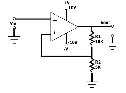
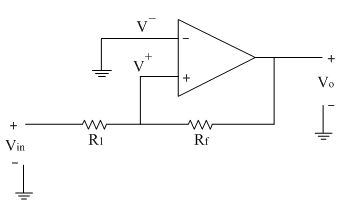
Thus will get the negative half of the square wave as shown in figure b. 2 Answers to the two Sections should be written in separate books. As this resistive network is connected between the amplifiers output and non-inverting input when Vout is saturated at the positive supply rail a positive voltage is applied to the op-amps non-inverting input.
The datasheet tells us that a logic high input will be det. The circuit diagram PCB for Eagle Version 590 free edition modified firmware and photos are in this zipped archive. A positive-going signal at the input of an inverting amplifier would result in a negative-going signal at the output and vice.
The inverting amplifier is an important circuit configuration using op-amps and it uses a negative feedback connection. Excited to start this journey. The main application of this circuit is in automobiles as an anti theft alarm.
Optocouplers featuring Schmitt trigger property are also available. In this circuit as the shock sensor a piezoelectric sensor is used that has to fixed on the door which you have to guard. An important application is the Schmitt Trigger circuit.
In electronics a Schmitt trigger is a comparator circuit with hysteresis implemented by applying positive feedback to the noninverting input of a comparator or differential amplifier. A 16 log10 a. Using a calculator determine the antilogarithm of the following expressions.
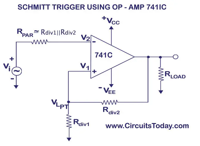
Inverting Op-Amp Gain Table Calculator Excel Spread Sheet. Schmitt Trigger Equations and Calculator. While if you take the case of general-purpose op-amp like LM 741 in which the input bias current used to be in the range of nano-amperesWhile if you see the high-precision op-amps like AD 549 in that case the input bias current used to be in the range of famto-amperes.
The circuit is named a trigger because the output retains its value until the input changes sufficiently to trigger a change. Ohms Law Equation and Calculator. Solution a a 1016 Calculator keys.
4 Black figures to the right indicate full marks. Simple implantation calculator. 6 Assume suitable data if necessary.
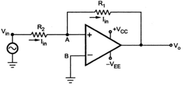
The inverting input becomes greater than the non-inverting input and hence op-amp output switches to negative voltage and gets amplified till V out max. Note that this calculator can be used for either an inverting or a non-inverting op-amp configuration. For a non-inverting op-amp set V2 to 0V and use V1 as the input.
B 004 loge a. Linear Circuit Source Calculator Excel Spreadsheet. If an inverting op-amp is desired set V1 to 0V and use V2 as the input.
Here LM358 is connected as an inverting Schmitt trigger. Op Amp based Schmitt Trigger Circuits. Five simple yet effective electronic toggle flip flop switch circuits can be built around the IC 4017 IC 4093 and IC 4013.
Academiaedu is a platform for academics to share research papers. It is an active circuit which converts an analog input signal to a digital output signal. Click on the buttons in the Truth Table or in the Karnaugh Map to change the value.
3 Neat diagrams must be drawn wherever necessary. It was tested up to 172 MHz but may possibly work up to 200 MHz. The resulting values are in kilo-ohms kΩ.
By changing the values of R C1 and R C2 the amount of hysteresis can be controlled while the value of R E can be used to increase the Upper Threshold Voltage. The inverting terminal of the lower comparator is connected to the external trigger input pin whereas the non-inverting terminal is connected to the point with DC potential of 13 V CC. 1786 Likes 63 Comments - Mitch Herbert mitchmherbert on Instagram.
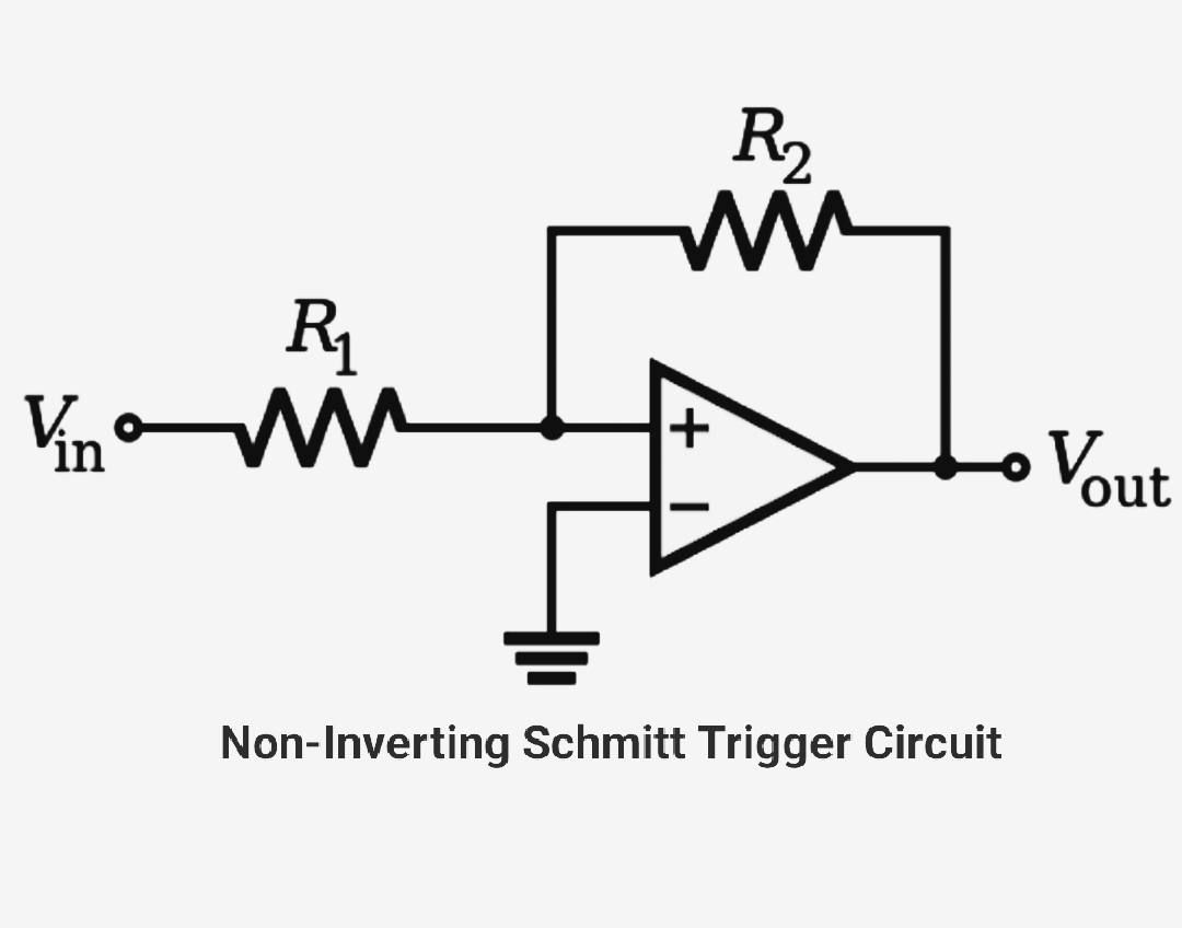
Wheatstone Bridge Analysis and Calculator. Since a Schmitt trigger circuit is essentially an amplifier with positive feedback it is possible to implement this setup using operational amplifiers or simply Op Amps. The op-amp comparator circuit above is configured as a Schmitt trigger that uses positive feedback provided by resistors R1 and R2 to generate hysteresis.
This is the application of an op-amp as a square wave generator.
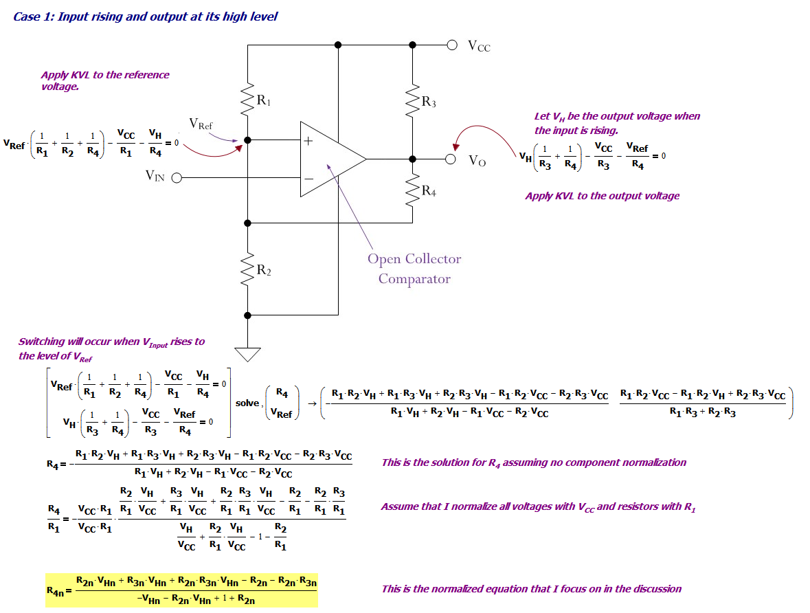
Schmitt Trigger Design Math Math Encounters Blog
Schmitt Trigger Working With Ic555 Transistors And Applications

Schmitt Trigger Uses Two Transistors Edn
Basics Of Schmitt Trigger How Schmitt Trigger Works
The Schmitt Trigger

Schmitt Trigger Circuit Using Ua741 Op Amp Ic Design Diagram Working
Schmitt Trigger Circuit Working And Applications Electronic Devices
Non Inverting Schmitt Trigger Analog Integrated Circuits Electronics Tutorial


