
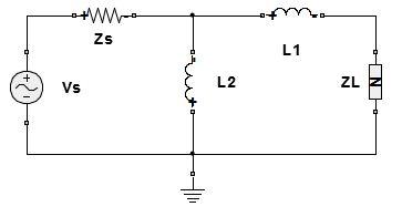
Unlike the L filter where only one combination of L and C gave the required impedance matching at a given frequency the PI filter allows for multiple combinations of C1 C2 and L to achieve the desired impedance matching each combination having a different Q. Achieved by designing a matching network or circuit between the feed line and the antenna.

Methodology For Broadband Matching Of Electrically Small Antenna Using Combined Non Foster And Passive Networks Springerlink

Antenna Design Workflow Using Full Wave Matching Circuit Optimization Remcom Archived Webinars
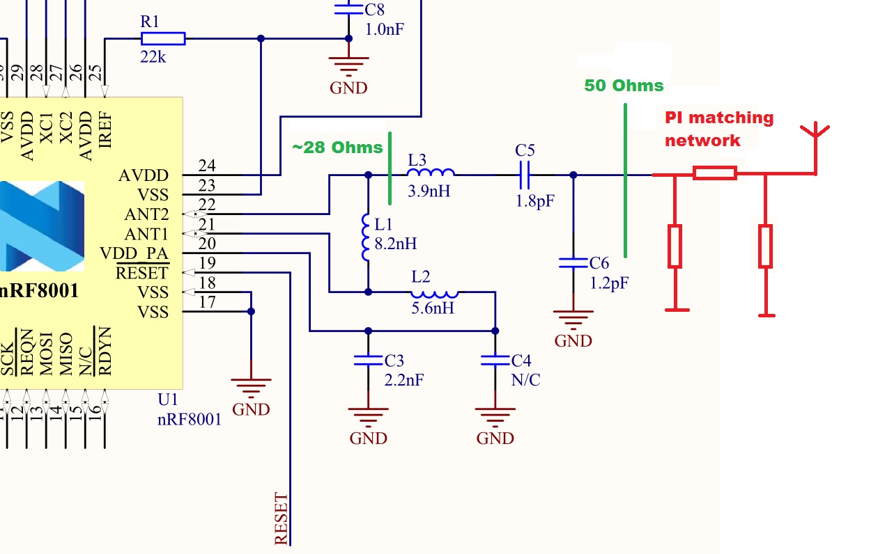
Pcb Antenna Matching Circuit For Nrf8001 Nordic Q A Nordic Devzone Nordic Devzone
The toolbox lets you integrate antenna array patterns into wireless systems for simulating beamforming and beam steering algorithms.

Antenna matching circuit. The Antenna Downtilt and Coverage Calculator aka Antenna Tilt Angle Calculator is used to determine the approximate downward angle measured in degrees which the transmitting antenna is to be positioned for optimal signal strength and coverageThis antenna tilt angle calculator also provides given a beam width the inner and outer radii of beams. Circuit Diagram of 2 km FM Transmitter Circuit. This is a trace drawn on the PCBThis can bea straight trace inverted F -type trace meandered trace circular trace or a curve withwiggles depending on the antenna type and space constraints.
Between the antenna high impedance to the operating frequency Because the length is too large to match the input impedance of the radio receiver. How TV Transmitter Circuit Works. This specific type of matching is known as a Fuchskreis and was invented by an Austrian fellow called Joseph Fuchs OE1JF in 1927.
This resistance is in parallel with the dynamic resistance of the tuned circuit and so it lowers the Q or resonant impedance of the resonant circuit so reducing the gain to the extent that the circuit will not oscillate. Antenna Downtilt and Coverage Calculator. In fact any.
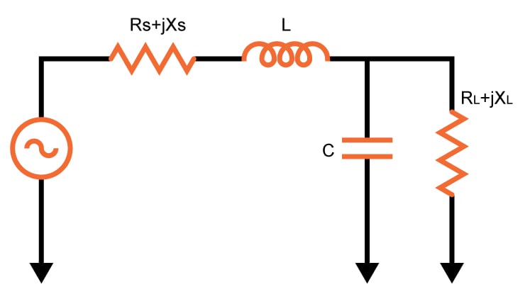
Impedance Matching Methods Antenna impedance is complex consisting of both resistive and reactive parts so the matching network must include components of both to achieve. Returning to Figure 1114 the microstrip feed is inset into the antenna a distance x to obtain an input match. The balanced nature of the ideal circuit ensures that identical current will exist on each side of the dipole.
Figure 71 illustrates operation of a basic half-wave resonant dipole antenna. The MFJ-949E is a 300 watt RF output power antenna tuner that will match any transmitter or transceiver to virtually any antenna. As stated previously the impedance is a fundamental parameter for antennas.
Impedance Matching was originally developed for electrical power but can be applied to any other field where a form of energy not necessarily electrical is transferred between a source and a load. Nowadays the Pi network is not popular for use a matching network in antenna tuners because the variable capacitors required in the circuit become large large for the lower frequencies in the HF portion of the spectrum and these are costly. Matching Network RF design is all about impedance matching Inductors and capacitors are handy elements at impedance matching.
The dimension b is chosen so that the cavity formed by the conductor on the top plane of the structure is resonant. The PI filter is a very versatile matching circuit it consists of 3 reactive elements usually two capacitors and one inductor. This antenna which works on 10 15 20 and 40 meters has a very high impedance of around 2500 Ohms.
The impedance analysis results can be used to design matching networks for integration with the RF. If the impedance of an antenna is not close to that of the transmission line most often 50 Ohms then very little power will be transmitted by the antenna if the antenna is used in the transmit mode or very little power will be. This format pf matching was widely used as the output tuning for vintage tube of valve based transmitters.
High Gain Wideband Active Antenna amplifier. The inverted-F antenna was first proposed in 1958 by the group at Harvard led by Ronold W. The MFJ-949E uses a T matching network and covers all bands between 160 and 10 meters.
The kit includes the parts needed to construct a 491 impedance matching network which will transform the impedance to 50 Ohms which will suit most transceivers. A simple and intuitive technique for modeling this antenna is the. The inverted-F antenna combines the advantages of both these antennae.
Being able to feed the dipole from one end gives you more options on how to erect an antenna and makes portable operation easier. In addition this signal amplifier from this antenna also useful as impedance matching. The frequency is set at anywhere between the FM frequency range from 88MHz to 108MHz.
Hence by shortening the slot I basically improved the impedance matching of the dipole antenna mode - and I also now know that the dipole antenna mode occurs at 1 GHz and the slotifa antenna mode occurs at about 35 GHz. An antenna coupling network is a passive network generally a combination of inductive and capacitive circuit elements used for impedance matching in between the antenna and the transmitter or receiver. This causes radiation at the two edges of the antenna as shown by the fringing fields in the diagram.
The matching circuit is well described in the ESP8266 Hardwear Design Guide. Optenni Lab Innovation leader in RF Design Automation Optennis main product Optenni Lab is the leading RF Design Automation software platform that features automatic matching circuit synthesis and optimization antenna array beamforming with active impedance control and many assessment tools to evaluate a design candidates RF performance. Current near the ends of the dipole is of necessity small vanishing at the ends because electrons whose movement constitutes the.
Without loss of generality assume R S R L and a power match factor of m R SR L is desired. For a quarter wavelength Wi-Fi antenna the theoretical length should be 3125mm. The power of the FM signal from the oscillator is then amplified using a power amplifier to produce a low impedance output matching that with the antenna.
It has the compactness of the inverted-L and the capability of matching the impedance of the feed circuit typically 50 Ω for printed circuitry like the F-type. Either a tapped resonant circuit a Zepp type coupling circuit or a high impedance ratio UNUN 491 or 641 It can be used on multiple bands. In this section well be concerned with measuring the impedance of an antenna.
The antenna has shunt resistance and without the ant coupling cap this is connected across the resonant circuit. The capacitor and inductor create a resonant circuit. By matching the dipole feed impedance or dipole characteristic impedance to the source or load the antenna is able to operate to its maximum efficiency.
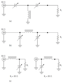
Lets look at the second circuit. A Smith chart can be used to determine matching network lumped element values. The outdoor FM antenna is actually designed and manufactured for giving the best and outstanding reception for all the FM broadcast stations.
Shown in Figure 71a is a dipole antenna excited from an RF source. Omnidirectional outdoor FM aerial antenna means that the outdoor antenna will be rotating in all directions and helps in obtaining the signals from the tower and thus provides the best signal strength and distortion fewer signals. If fed at the end aka EFHW antenna impedance is in the 2000-4000 ohms range.
The first Impedance Matching concept in RF domain was related to Antenna Matching. Peak or average forward and reflected power and SWR can be read on the illuminated cross-needle meter. In order to ensure that impedance matching is maintained there are several ways in which a dipole can be fed by its feeder.
Initially I thought to make the PCB a little bit smaller to do so I was searching for some reference design thats why its written 23mm. Viewed as a black-box an impedance matcher changes a given load resistance R L to a source resistance R S. Antenna geometry and analysis results can be visualized in 2D and 3D.
It requires a high impedance matching device. In Figure 6 the antenna resembles a dipole antenna that has the short circuit to the left the inductive path.
Ic Antenna Matching Circuit Nordic Q A Nordic Devzone Nordic Devzone

Impedance Matching Circuit Of The Emitter Antenna Download Scientific Diagram

Trf7970a Antenna Impedance Matching Other Wireless Technologies Forum Other Wireless Ti E2e Support Forums
Impedance Matching Of Small Monopole Antenna Matlab Simulink
Automatic Impedance Matching In Rf Design Electronic Design

Pseudo Differential Model Of The Antenna Matching Network And The Load Download Scientific Diagram
L Match Impedance Matching Circuits Electrical Engineering Electronics Tools
Recommended External Antenna Matching Network Silicon Labs


